G Pulla Reddy Engineering College

Electrical Machines – Virtual Laboratory

Hopkinson's Test

Back-to-Back Test for DC Machine Efficiency

🎯 Aim

To determine the efficiency of two identical DC machines (motor and generator) using Hopkinson's test (back-to-back test or regenerative test).

Objectives:

  • To determine the efficiency of both machines simultaneously
  • To measure the losses of both machines
  • To test machines at full-load conditions economically
  • To understand the regenerative method of testing

📖 Theory

Introduction

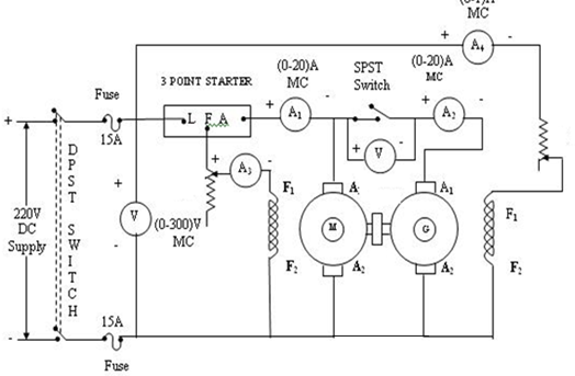
Hopkinson's test is a regenerative test method used to determine the efficiency of two identical DC machines. One machine acts as a motor driving the other machine which acts as a generator. The generator feeds back power to the motor, making this test very economical.

Principle

In this test, two identical DC machines are mechanically coupled. One machine (M) runs as a motor and drives the other machine (G) which runs as a generator. The generator supplies power back to the motor, and only the losses need to be supplied from the external source.

Key Formulas

Power Supplied from Source:

Pinput = V ×  Iinput watts

This power supplies only the losses of both machines

Total Losses:

Ploss = Pinput = Losses of Motor + Losses of Generator

Motor Input Power:

PM_in = V ×  IM watts

Generator Output Power:

PG_out = V ×  IG watts

Motor Output Power:

PM_out = PG_out + Mechanical losses

Motor Efficiency:

ηM = PM_out / PM_in ×  100%

Generator Efficiency:

ηG = PG_out / PG_in ×  100%

Assuming Equal Losses:

Losses per machine = Pinput / 2

Motor efficiency: ηM = (PM_in - Ploss/2) / PM_in ×  100%

Generator efficiency: ηG = PG_out / (PG_out + Ploss/2) ×  100%

Advantages

  • Very economical - requires only losses to be supplied
  • Both machines can be tested at full-load conditions
  • No need for external loading arrangement
  • Continuous operation possible
  • Temperature rise can be observed

Disadvantages

  • Requires two identical machines
  • Cannot separate losses of individual machines easily
  • Assumes equal losses in both machines
  • More complex connections

📜 Procedure

Apparatus Required

  • Two Identical DC Machines (Shunt motors/generators)
  • DC Supply (Variable)
  • Field Rheostats (2 nos.)
  • Voltmeters (2-3 nos.)
  • Ammeters (4-5 nos.)
  • Wattmeter (optional)
  • Coupling arrangement
  • Connecting wires

Circuit Diagram

Circuit Diagram

Steps

  1. Connection Setup:
    • Connect the two machines mechanically (couple them)
    • Connect Machine M (Motor) to DC supply
    • Connect Machine G (Generator) in parallel with Motor
    • Connect field rheostats for both machines
    • Connect voltmeters and ammeters as per circuit diagram
    • Ensure all connections are correct and secure
  2. Starting Procedure:
    • Set both field rheostats to maximum resistance
    • Close the switch to start Machine M (Motor)
    • Adjust the field of Motor to get desired speed
    • Excite the Generator field separately
    • Adjust Generator field to build up voltage
    • Close the switch to connect Generator to Motor
  3. Loading Test:
    • Adjust the field currents to vary the load
    • For each load condition, note down:
      • Supply voltage (V)
      • Input current from supply (Iinput)
      • Motor current (IM)
      • Generator current (IG)
      • Motor field current (IfM)
      • Generator field current (IfG)
      • Speed (N)
    • Take readings for different load conditions
  4. Observations:
    • Record all readings in a tabular format
    • Calculate input power, output power, and losses
    • Calculate efficiency of both machines
    • Plot efficiency vs. load curves

Precautions

  • Ensure both machines are identical
  • Check all connections before starting
  • Start with minimum field current
  • Do not exceed rated current and voltage
  • Ensure proper coupling between machines
  • Monitor temperature rise during test
  • Adjust fields gradually

📊 Sample Calculations

Given Data

Parameter Value
Rated Voltage (V) 220 V
Rated Current (I) 10 A
Rated Power 2 HP (1492 W)
Rated Speed 1500 RPM

Test Reading

Parameter Value
Supply Voltage (V) 220 V
Input Current from Supply (Iinput) 3.5 A
Motor Current (IM) 10 A
Generator Current (IG) 9.5 A
Motor Field Current (IfM) 0.5 A
Generator Field Current (IfG) 0.5 A
Speed (N) 1500 RPM

Calculations

Step 1: Calculate Power Supplied from Source

Pinput = V ×  Iinput = 220 ×  3.5 = 770 W

This power supplies only the losses of both machines

Step 2: Calculate Total Losses

Ploss_total = Pinput = 770 W

Assuming equal losses: Losses per machine = 770 / 2 = 385 W

Step 3: Calculate Motor Input Power

PM_in = V ×  IM = 220 ×  10 = 2200 W

Step 4: Calculate Generator Output Power

PG_out = V ×  IG = 220 ×  9.5 = 2090 W

Step 5: Calculate Motor Output Power

Motor output = Generator input (approximately)

PM_out ≈ PG_out + Mechanical losses

For calculation: PM_out = PM_in - LossesM

PM_out = 2200 - 385 = 1815 W

Step 6: Calculate Generator Input Power

PG_in = PG_out + LossesG

PG_in = 2090 + 385 = 2475 W

Step 7: Calculate Motor Efficiency

ηM = (PM_out / PM_in) ×  100%

ηM = (1815 / 2200) ×  100% = 82.5%

Step 8: Calculate Generator Efficiency

ηG = (PG_out / PG_in) ×  100%

ηG = (2090 / 2475) ×  100% = 84.4%

Step 9: Verification

Motor input = 2200 W

Generator output = 2090 W

Power from supply = 770 W

Check: Motor input = Generator output + Power from supply

2200 ≈ 2090 + 770 = 2860 (difference due to losses)

Actually: Motor input = Generator output + Total losses

2200 = 2090 + 110 (difference in currents ×  voltage)

Expected Results

  • Power from supply is only a fraction of rated power (typically 10-20%)
  • Efficiency of both machines is typically 75-85%
  • Motor and generator efficiencies are approximately equal
  • Total losses can be directly measured from supply power
  • This method is very economical for testing large machines
🚀 Start Simulation
🏠 Back to Home