G Pulla Reddy Engineering College

Electrical Machines – Virtual Laboratory

Transformer Open Circuit Test

No-Load Test for Core Losses and Magnetizing Current

🎯 Aim

To determine the iron losses (core losses), no-load current, no-load power factor, and magnetizing component of the no-load current of a transformer.

Objectives:

  • To measure the core losses (hysteresis and eddy current losses)
  • To determine the no-load power factor
  • To find the magnetizing current and core loss component of no-load current
  • To calculate the equivalent circuit parameters (R0 and X0)

📖 Theory

Introduction

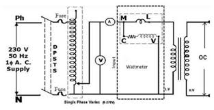
The open circuit test (O.C. test) is performed on the low-voltage side of the transformer with the high-voltage side left open. This test helps determine the core losses and no-load parameters of the transformer.

Principle

When the transformer is energized at rated voltage with the secondary open-circuited, the primary draws a small current called no-load current (I0). This current has two components:

  • Magnetizing component (Im): Creates the flux (90° lagging)
  • Core loss component (Iw): Supplies the core losses (in phase with voltage)

Key Formulas

No-Load Power:

P0 = V1 ×  I0 ×  cos f0 watts

Where: V1 = Applied voltage, I0 = No-load current, cos f0 = No-load power factor

Core Losses (Pc):

Pc = P0 ≈ Iron losses

Since copper losses are negligible at no-load

No-Load Power Factor:

cos f0 = P0 / (V1 ×  I0)

Core Loss Component:

Iw = I0 cos f0 = P0 / V1

Magnetizing Component:

Im = I0 sin f0 = v(I0² - Iw²)

Equivalent Circuit Parameters:

R0 = V1 / Iw = V1² / P0

X0 = V1 / Im

Advantages

  • Simple test requiring only voltmeter, ammeter, and wattmeter
  • Performed at low voltage, so safer
  • Direct measurement of core losses
  • Helps in determining transformer efficiency

Core Losses Components

  • Hysteresis Loss: Due to magnetic reversal in core material
  • Eddy Current Loss: Due to induced currents in core laminations

📜 Procedure

Apparatus Required

  • Single-phase Transformer
  • AC Supply (Variable)
  • Voltmeter (2 nos.)
  • Ammeter
  • Wattmeter
  • Connecting wires

Circuit Diagram

Circuit Diagram

Steps

  1. Connection Setup:
    • Connect the low-voltage (LV) winding to the AC supply
    • Keep the high-voltage (HV) winding open-circuited
    • Connect voltmeter V1 across LV winding
    • Connect voltmeter V2 across HV winding (to verify transformation ratio)
    • Connect ammeter in series with LV winding
    • Connect wattmeter with proper connections
  2. Test Procedure:
    • Start with zero voltage
    • Gradually increase the supply voltage to rated value
    • Ensure the transformer is operating at rated frequency
    • Allow the transformer to stabilize
    • Note down the following readings:
      • Primary voltage (V1)
      • Secondary voltage (V2)
      • No-load current (I0)
      • No-load power (P0)
  3. Variation Test (Optional):
    • Vary the applied voltage from 50% to 110% of rated voltage
    • Take readings at different voltage levels
    • Observe how core losses vary with voltage
  4. Observations:
    • Record all readings in a tabular format
    • Calculate no-load power factor, Iw, Im
    • Calculate equivalent circuit parameters
    • Plot P0 vs V1 curve

Precautions

  • Always perform test on LV side for safety
  • Ensure HV side is completely open
  • Apply voltage gradually
  • Check wattmeter connections (current and voltage coils)
  • Ensure rated frequency is maintained
  • Allow transformer to reach steady state before taking readings

📊 Sample Calculations

Given Data

Parameter Value
Transformer Rating 5 kVA
Primary Voltage (V1) 230 V
Secondary Voltage (V2) 115 V
Frequency 50 Hz

Open Circuit Test Reading

Parameter Value
Applied Voltage (V1) 230 V
Secondary Voltage (V2) 115 V
No-Load Current (I0) 0.8 A
No-Load Power (P0) 45 W

Calculations

Step 1: Calculate No-Load Power Factor

cos f0 = P0 / (V1 ×  I0)

cos f0 = 45 / (230 ×  0.8) = 45 / 184 = 0.2446

f0 = cos-1(0.2446) = 75.84°

Step 2: Calculate Core Loss Component (Iw)

Iw = I0 cos f0 = 0.8 ×  0.2446 = 0.196 A

Or: Iw = P0 / V1 = 45 / 230 = 0.196 A

Step 3: Calculate Magnetizing Component (Im)

Im = I0 sin f0 = 0.8 ×  sin(75.84°) = 0.8 ×  0.9698 = 0.776 A

Or: Im = v(I0² - Iw²) = v(0.8² - 0.196²) = v(0.64 - 0.0384) = v0.6016 = 0.776 A

Step 4: Calculate Core Losses

Pc = P0 = 45 W

(Since copper losses are negligible at no-load)

Step 5: Calculate Equivalent Circuit Parameters

R0 = V1 / Iw = 230 / 0.196 = 1173.5 Ω

Or: R0 = V1² / P0 = (230)² / 45 = 52900 / 45 = 1175.6 Ω

X0 = V1 / Im = 230 / 0.776 = 296.4 Ω

Step 6: Verify Transformation Ratio

K = V2 / V1 = 115 / 230 = 0.5

Or: K = N2 / N1 = 0.5 (Step-down transformer)

Expected Results

  • No-load current is typically 2-5% of full-load current
  • No-load power factor is very low (0.1 to 0.3)
  • Core losses remain approximately constant at all loads
  • Im >> Iw (magnetizing component is much larger)
  • Core losses vary approximately as V² (eddy current) and V1.6 (hysteresis)
🚀 Start Simulation
🏠 Back to Home