G Pulla Reddy Engineering College

Electrical Machines – Virtual Laboratory

Transformer Short Circuit Test

Impedance Test for Copper Losses and Equivalent Parameters

🎯 Aim

To determine the copper losses (full-load copper losses), equivalent resistance, equivalent reactance, and equivalent impedance of a transformer.

Objectives:

  • To measure the copper losses at full-load current
  • To determine the equivalent circuit parameters (R01, X01, Z01)
  • To calculate the voltage regulation
  • To find the short circuit current and percentage impedance

📖 Theory

Introduction

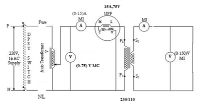
The short circuit test (S.C. test) is performed on the high-voltage side of the transformer with the low-voltage side short-circuited. This test helps determine the copper losses and equivalent impedance parameters of the transformer.

Principle

When the transformer secondary is short-circuited and a reduced voltage is applied to the primary, the current drawn is the full-load current. At this condition:

  • Core losses are negligible (since applied voltage is very low)
  • Power input is approximately equal to copper losses
  • The voltage required is typically 5-10% of rated voltage

Key Formulas

Short Circuit Power:

Psc = Vsc ×  Isc ×  cos fsc watts

Where: Vsc = Short circuit voltage, Isc = Short circuit current

Copper Losses (Pcu):

Pcu = Psc ≈ Full-load copper losses

Since core losses are negligible at low voltage

Equivalent Impedance:

Z01 = Vsc / Isc O

Referred to primary side

Equivalent Resistance:

R01 = Psc / Isc² = Vsc cos fsc / Isc O

Equivalent Reactance:

X01 = v(Z01² - R01²) O

Percentage Impedance:

%Z = (Vsc / Vrated) ×  100%

Voltage Regulation:

% Regulation = (I1R01 cos f ± I1X01 sin f) / V1 ×  100%

+ for lagging power factor, - for leading power factor

Advantages

  • Performed at low voltage, so safe and economical
  • Direct measurement of copper losses
  • Helps in determining voltage regulation
  • Essential for transformer design and protection

Applications

  • Determining transformer efficiency
  • Calculating voltage regulation
  • Designing protection systems
  • Parallel operation of transformers

📜 Procedure

Apparatus Required

  • Single-phase Transformer
  • AC Supply (Variable, low voltage)
  • Voltmeter
  • Ammeter
  • Wattmeter
  • Short-circuiting link/connector
  • Connecting wires

Circuit Diagram

Circuit Diagram

Steps

  1. Connection Setup:
    • Connect the high-voltage (HV) winding to the AC supply
    • Short-circuit the low-voltage (LV) winding using a thick conductor
    • Connect voltmeter across HV winding
    • Connect ammeter in series with HV winding
    • Connect wattmeter with proper connections
    • Ensure all connections are tight and secure
  2. Test Procedure:
    • Start with zero voltage
    • Gradually increase the supply voltage
    • Monitor the ammeter reading
    • Increase voltage until the current reaches full-load current (IFL)
    • Note: The voltage required will be very low (typically 5-10% of rated voltage)
    • Note down the following readings:
      • Short circuit voltage (Vsc)
      • Short circuit current (Isc)
      • Short circuit power (Psc)
  3. Variation Test (Optional):
    • Take readings at different current levels (50%, 75%, 100%, 125% of full-load)
    • Observe how copper losses vary with current
    • Verify that Pcu ? I²
  4. Observations:
    • Record all readings in a tabular format
    • Calculate equivalent circuit parameters
    • Calculate percentage impedance
    • Plot Psc vs Isc curve

Precautions

  • Always perform test on HV side for safety
  • Ensure LV side is properly short-circuited
  • Apply voltage very gradually
  • Do not exceed full-load current
  • Use thick conductor for short-circuiting
  • Ensure rated frequency is maintained
  • Test duration should be short to avoid overheating

📊 Sample Calculations

Given Data

Parameter Value
Transformer Rating 5 kVA
Primary Voltage (V1) 230 V
Secondary Voltage (V2) 115 V
Full-Load Current (Primary) 21.74 A
Frequency 50 Hz

Short Circuit Test Reading

Parameter Value
Short Circuit Voltage (Vsc) 18 V
Short Circuit Current (Isc) 21.74 A
Short Circuit Power (Psc) 280 W

Calculations

Step 1: Calculate Short Circuit Power Factor

cos fsc = Psc / (Vsc ×  Isc)

cos fsc = 280 / (18 ×  21.74) = 280 / 391.32 = 0.715

fsc = cos-1(0.715) = 44.4°

Step 2: Calculate Copper Losses

Pcu = Psc = 280 W

(Since core losses are negligible at low voltage)

Step 3: Calculate Equivalent Impedance

Z01 = Vsc / Isc = 18 / 21.74 = 0.828 Ω

Step 4: Calculate Equivalent Resistance

R01 = Psc / Isc² = 280 / (21.74)² = 280 / 472.9 = 0.592 Ω

Or: R01 = Z01 cos fsc = 0.828 ×  0.715 = 0.592 Ω

Step 5: Calculate Equivalent Reactance

X01 = v(Z01² - R01²)

X01 = v(0.828² - 0.592²) = v(0.685 - 0.350) = v0.335 = 0.579 Ω

Or: X01 = Z01 sin fsc = 0.828 ×  sin(44.4°) = 0.828 ×  0.699 = 0.579 Ω

Step 6: Calculate Percentage Impedance

%Z = (Vsc / Vrated) ×  100%

%Z = (18 / 230) ×  100% = 7.83%

Step 7: Calculate Voltage Regulation (at unity power factor)

% Regulation = (I1R01 cos f + I1X01 sin f) / V1 ×  100%

At unity p.f., cos f = 1, sin f = 0

% Regulation = (I1R01) / V1 ×  100%

% Regulation = (21.74 ×  0.592) / 230 ×  100% = 12.87 / 230 ×  100% = 5.59%

Step 8: Calculate Voltage Regulation (at 0.8 lagging power factor)

cos f = 0.8, sin f = 0.6

% Regulation = (I1R01 cos f + I1X01 sin f) / V1 ×  100%

% Regulation = (21.74 ×  0.592 ×  0.8 + 21.74 ×  0.579 ×  0.6) / 230 ×  100%

% Regulation = (10.3 + 7.55) / 230 ×  100% = 17.85 / 230 ×  100% = 7.76%

Expected Results

  • Copper losses vary as I² (square of current)
  • Percentage impedance typically ranges from 3% to 10%
  • Voltage regulation is better at leading power factor than lagging
  • Equivalent resistance and reactance help in determining transformer performance
  • Short circuit voltage is typically 5-10% of rated voltage
🚀 Start Simulation
🏠 Back to Home